BiSS Interface
// Overview
What is the BiSS Interface?
BiSS (Bidirectional/Serial/Synchronous) is a digital, serial interface protocol for fast and safe isochronous process data transmission, particularly used in motor feedback systems. Simultaneous to the reception of sensor process data and the transmission of actuator process data in real-time, the BiSS protocol is capable of register data transfers without interrupting the process data stream.
// Topologies
Point-to-Point and Bus Connection
a) Point-to-Point Connection
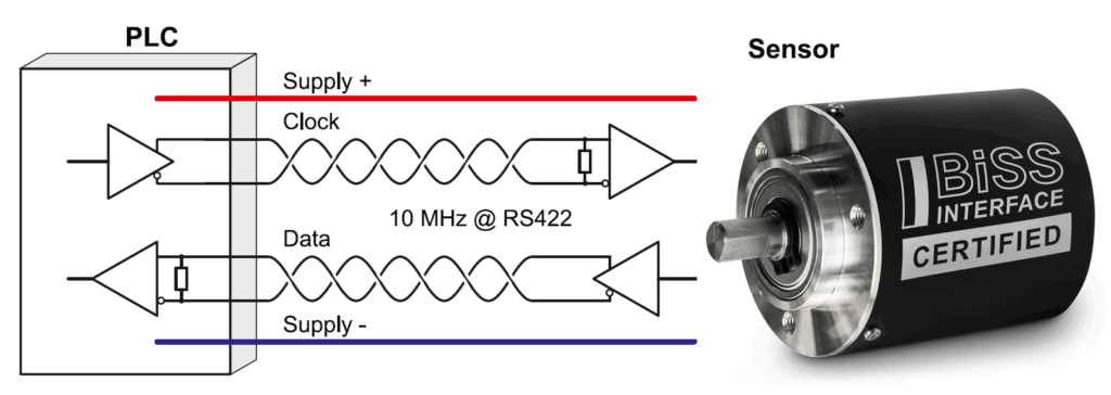
In the point-to-point connection only one sensor device is connected to the master device using one clock line and one data output line. Within the sensor device, several sensors can be daisy-chained, e.g. to enable redundant data transmission for safety ystems, smart sensor applications or condition monitoring.
b) Bus Connection
For systems with more than one sensor device, the bus connection is used. In contrast to the point-to-point connection, the bus connection requires a third line (data input) to delay the start bit for proper process data transmission. The third line also enables data transmission to actuator devices.
// BiSS Frame and Features
BiSS Interface at a Glance
Latch Point
Sensor data is simultaneously captured for all slaves in the daisy chain with the first rising edge of the clock signal (MA).
Line Delay Compensation
The BiSS master measures and compensates the total line delay in every frame. The line delay is measured from second rising edge of the clock signal (MA) to falling edge of the data output signal (SL) and takes propagation delays, aging effects and temperature effects into account.
Slave Processing Time
In a point-to-point topology the slave can delay the start bit, if it requires time to prepare and provide its sensor data. This feature enables preprocessing of sensor data before transmission.
Data Channel
Sensor and actuator data are transmitted as part of a data channel. Each data channel is defined by its communication parameters, e.g. transmission direction (sensor or actuator data), data length (0...64 bit), CRC polynomial (0...16 bit). BiSS can be used for arbitrary sensor and actuator data, e.g. position, torque and rotation speed. For standardization, the data contents are described in application specific BiSS Profiles.
Control Communication
BiSS enables a bidirectional control communication via the unidirectional clock (MA) and data output line (SL). In each frame the master sends one control data bit to the slave (CDM) and the slave responds with its control data bit (CDS). This in-band protocol can be used to perform register accesses to the slave without interrupting the process data transfer. For example, it enables access to a sensor’s electronic datasheet, reading a sensor’s temperature register or calibration.
Plug & Play
Control communication enables a BiSS master to access the slave’s memory. Typically, the sensor/actuator manufacturer stores product specific data, e.g. a manufacturer ID, device ID, serial number and a standardized electronic datasheet (EDS) in the slave’s non-volatile memory (e.g. EEPROM). The EDS contains all equired parameters to successfully establish BiSS communication between master and slave and additionally provides application specific parameters. On power-up, the BiSS master can automatically read the EDS and configure itself accordingly, in order to support user-friendly plug & play operation.
Timeout
Each BiSS frame is terminated by the slave’s timeout. The timeout is either a constant period (typically about 20 µs) or depends on the clock frequency applied to the clock line (adaptive timeout). The adaptive timeout significantly reduces the timeout period at high frequencies, resulting in short cycle times well below 10 µs.
// Learn more about...
The BiSS Interface Platform

BiSS Safety
BiSS Safety is a profile definition for BiSS that has been certified by TÜV Rheinland for safety-critical applications up to SIL3 according to IEC61508:2010. BiSS Safety defines the data channel contents in order to ensure failure mode detection as defined in IEC61784-3 using redundant position words, different CRC polynomials and a sign-of-life counter.

BiSS Line
BiSS Line is a one-cable technology based on BiSS. It enables a combined power and data transmission over just two wires based on the RS485 half-duplex transmission standard. BiSS Line is fully compatible to BiSS and all of its features including low jitter, control communication and short cycle times. Data availability is ensured by a forward error correction (FEC) which is suitable to repair up to four corrupted bytes.

