BiSS Safety
// Overview
The BiSS Safety Profile
BiSS Safety is a profile definition for BiSS that has been certified by TÜV Rheinland for safety-critical applications up to SIL3 according to IEC61508:2010. BiSS Safety uses the concept of a "Black Channel" transmission and specifies the data channel contents in order to ensure failure mode detection as defined in IEC61784-3 using redundant position words, different CRC polynomials and a sign-of-life counter. BiSS Safety is fully compatible with BiSS and all of its features including line delay compensation, processing times and daisy-chaining of additional sensors.
// System
The BiSS Safety System
Safety Sensor
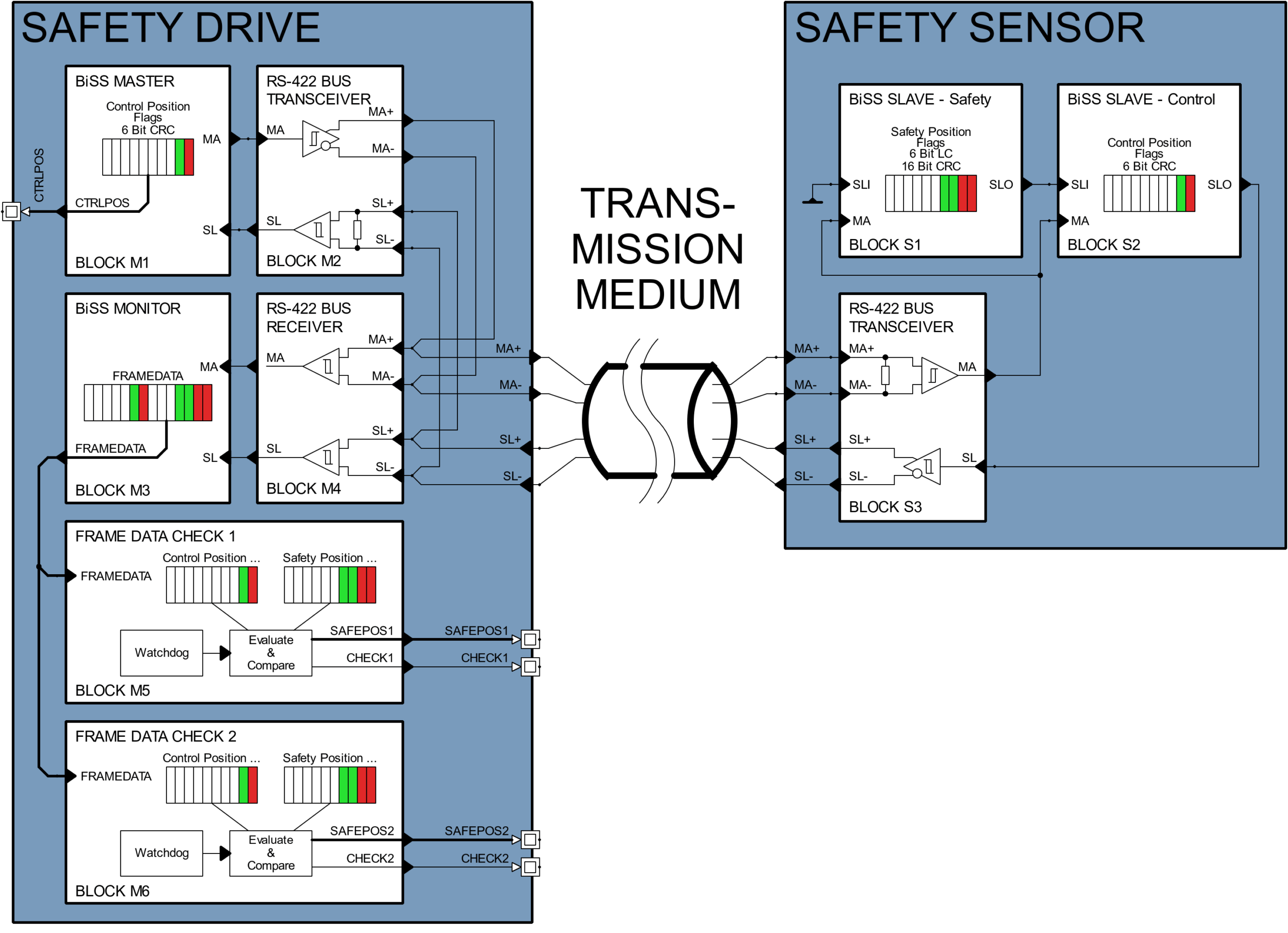
Two independent position words are generated by two daisy-chained sensors. One sensor generates the control position word (CPW) and the other sensor generates the safety position word (SPW). CPW and SPW are sent over a single cable from the safety sensor device on the right to the safety drive on the left.
Safety Drive
In this example, the safety drive contains the standard BiSS Master, a BiSS Monitor and two instances for Frame Data Checks (e.g. safe MCUs). The BiSS Master initiates the BiSS communication. The BiSS Monitor observes the BiSS transmission and provides the data channel contents to the Frame Data Check. Additionally, the monitor can provide safety functions and features to support a safe operation, e.g. it may check validity of the BiSS frame and indicate errors in case of issues. Both data channels are evaluated by the redundant Frame Data Check units. Each of them checks the data integrity by verifying CRC values, comparison of the position words and evaluation of the sign-of-life counter in order to detect possible transmission failures. The Frame Data Check instances signal their results and the safe position value to the superordinated control for further processing and actions.
// Data Channels
Redundant Position Words
In a typical BiSS Safety application two independent rotary position words are generated. Each position word is generated by one sensor and transmitted in a separate data channel along with additional data for failure mode detection.
Control Position Word (CPW)
Usually, the CPW is a high resolution position word and used for motor feedback. It may contain multiturn information (MT), which is the number of full mechanical revolutions, and singleturn information (ST), which is the angle information within one mechanical revolution. Validity of the position can be indicated to the BiSS master with an error (E) and a warning bit (W). Position, error bit and warning bit are protected against transmission errors with a standard 6-bit CRC (hamming distance = 3). Error bit, warning bit and CRC bits are inverted before transmission (indicated with bar).
Safety Position Word (SPW)
The SPW is used to verify the CPW generation and transmission. Typically, it contains position information with a lower resolution compared to the CPW. Validity of the position can be indicated to the BiSS master with an error (E) and a warning bit (W ). Additionally, an integrated 6-bit sign-of-life counter (LC) supports detection of missing or mixed up frames. Position, error bit, warning bit and sign-of-life counter are particularly protected with a safety capable 16-bit CRC (hamming distance = 6). Error bit, warning bit and CRC bits are inverted before transmission (indicated with bar).
// Safety
Failure Mode Detection
The following data channel contents are required to detect failure modes according to IEC61784-3.
Redundant Position Data
The independent generation of redundant position data is the key to implement safe transmission systems. However, not all bits of the redundant position words need to be compared. A minimum number of singleturn bits, which need to be suitable for comparison is defined (ACCMIN). The comparison of the CPW and SPW positions allows a +/- 1 least significant bit tolerance at ACCMIN.
Error and Warning Bits
Error and warning bit enable the sensor to provide status information to the BiSS master. An error indicates that the transmitted position data is invalid. The meaning of the warning bit may be defined by the sensor manufacturer, e.g. to inform the drive about an upcoming required maintenance.
Cyclic Redundancy Check (CRC)
The CRCs of both CPW and SPW have to be checked separately. Different CRC polynomials are used to securely identify CPW and SPW. The 6-bit CRC polynomial 0x43 is used for CPW and the 16-bit polynomial 0x190D9 is used for SPW.
Sign-of-Life Counter (LC)
The sign-of-life counter is incremented with every newly generated BiSS Frame. It can be compared to an expected counter value to detect missing and mixed up frames.
// Learn more about...
The BiSS Interface Platform

BiSS Interface
The BiSS (Bidirectional Serial Synchronous) Interface enables high-speed isochronous data transmissions for sensors and actuators. With features like line delay compensation, multi-slave capabilities and the possibility to access the memory ressources of the slaves, BiSS has become a popular global standard.

BiSS Line
BiSS Line is a one-cable technology based on BiSS. It enables a combined power and data transmission over just two wires based on the RS485 half-duplex transmission standard. BiSS Line is fully compatible to BiSS and all of its features including low jitter, control communication and short cycle times. Data availability is ensured by a forward error correction (FEC) which is suitable to repair up to four corrupted bytes.


