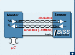
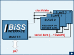
BiSS is an – Open Source – digital interface for sensors and actuators. BiSS is hardware compatible to the industrial standard SSI (Serial Synchronous Interface) but offers additional features and options:
- Bidirectional Data Communication
- Serial synchronous, continuous data communication
- Two unidirectional lines Clock and Data
- Cyclic at high speed (up to 10 MHz with RS422 and 100 MHz with LVDS)
- Line delay compensation for high speed data transfer
- Request processing times for data generation at slaves
- Safety capable: CRC, Errors, Warnings
- Bus capability for multiple slaves and devices in a chain
- Actuators
- Operate actuators via additional lines
Typical BiSS Applications
- Manufacturing Robotics Axis Motor Drives
- Motor feedback
- Servo Drives & Motion Control
- Position Encoders
- CNC Drives
The BiSS Interface
The BiSS Interface was introduced by iC-Haus as an Open-Source interface in 2002. The BiSS User Group was officially set up by formation of the BiSS Association e.V. in 2017 which pursues the BiSS Interface platform as an independent society. BiSS Association e.V. is enabled to confer free of charge BiSS licenses to device manufacturers and BiSS users following GPL-rules (General Public Licence).
The BiSS protocol is published in all details as Open-Source. The BiSS trademark and the IPs in the source code are placed at the disposal of appliance manufacturers. The biss-interface homepage gives up-to-date information on the licence model for trademarks and IPs, on available support and services, marketable products, such as microchips and smart sensors with BiSS, and available applications in industrial technology, such as encoders, motor control systems and controllers.
The Technology of BiSS
BiSS operates synchronously, serially and cyclically via two unidirectional lines. As the main feature BiSS in addition communicates continuously bidirectional (BiSS is the synonym for BiSS C; C = Continuously).
BiSS is hardware compatible to the standard SSI (Serial Synchronous Interface) and can moreover learn transmission times, thus clocking considerably faster depending on the line drivers used (up to 10 MHz with RS422 and 100 MHz with LVDS). BiSS can request processing times and is suitable for safety applications thanks to its CRC, error messaging and warning features. BiSS can also be used in sensor buses and can operate actuators via two additional lines.
BiSS Applications
BiSS is available as a sensor/actuator interface. With this development of the protocol in BiSS bidirectional parameters can be exchanged without the transmission of sensor data having to be interrupted or commands from the master to the slaves transmitted in the bus system. The technical disadvantage of mode setting in bidirectional interfaces is thus avoided, a disadvantage which lies in the interruption of a sensor data stream which can be particularly detrimental to fast digital control units in motor feedback systems, for example. A slave thus operates in a BiSS which is singularly defined and identical for each cycle. BiSS recognizes the end of a cycle as a TIMEOUT and uses the last recognized logic level as a control bit for the connected slaves which compile their control data words and commands across several isochronous cycles.
The processes and models which use BiSS have been lawfully patented for iC-Haus GmbH under DE 103 10 622 B4 and are a composite part of the free user license for manufacturers of appliances.
BiSS C Protocol Description (English)Digital sensor and actuator interface


Bidirectional digital sensor actuator interface BiSS safeguards communication between smart sensors like position encoders or measuring devices, actuators and industrial controls, such as a drive control, and is bus capable to serve sensors and actuators simultaneously. iC-Haus GmbH in Bodenheim, Germany published the open source protocol in 2002 offers master and slave Integrated Circuit devices, and licenses BiSS IP-modules as VHDL code also to other semiconductor and ASIC manufacturers. Licenses to device manufacturers and BiSS users following GPL-rules (General Public Licence) are free of charge.
For the in the Daisy Chain connected subscribers (Slaves) the interface master provides a clock signal for the simultaneous capture of all sensor data and for the synchronous-serial data transmission which follows on from this. Just two (resp. four with differential signals) unidirectional data lines are required; the slave electronics, kept to an absolute minimum, are incorporated on the sensor side or even within the smart sensor (three, resp. six RS422 data lines with actuator configuration). When the master sends a clock pulse on line MA, the slave answers directly on return line SL with the recorded sensor data.
Within each data cycle the master learns and compensates for line delays, thus permitting clock rates of up to 10 Mbit/s and also for cable lengths of up to 1000 m. Changes in line conditions which occur during cable drag, for example, are corrected. The precision of synchronization among several sensors is less than 1 microsecond; the master also makes the signal delay it has recorded accessible to the control unit, allowing further optimization. Permissable clock rates just depend on the drivers used and may exceed 100 MBit/s with LVDS signals.

The BiSS protocol classifies each subscriber in one of the following data sections: sensor data, actuator data, register data. These data sections have various setups with regard to access and transmission performance so that a number of different sensor applications are catered for.
Bidirectional parameter communication for device configuration – also applicable to what are known as OEM parameters – is usually consigned to the register data section. Rapidly changing sensor data being assigned to the sensor data section.
Control cycle times of less than 10 µs even at RS422 levels are thus not a problem, also for data words of up to 64 bits in length. There is enough room in the protocol for redundancy; this space is normally used to implement a CRC (cyclic redundancy check). Framed by start and stop bit, the sensor data is transmitted at the best-possible core data rate; a single multicycle data bit is optional for non-positioning measuring systems.
The individual user’s freedom of design for specific devices is not curbed by the need to keep solutions compatible with other BiSS products, thus also cutting down on unnecessary additional costs. A BiSS subscriber is defined in its entirety by just a few parameters; an XML device description file supplied with the sensor simplifies initial operation with a control system. If this does not yet have a BiSS input, BiSS devices can be switched over to SSI mode.
Further Information
The BiSS Interface Concept and the detailed BiSS Protocol Description are available in our Downloads section.
